 By Ben Lewis, KNX Consultants.
As a specialist in control and automation, and member of KNX UK Association, KNX is what we do, so visitors would expect to see it in our ‘home’. We recently moved our headquarters to Staunton near Gloucester, UK, and decided to take the opportunity to install KNX in the building. In this three-part series, I will cover the practicalities of controlling the building’s lighting and heating, and monitoring our energy consumption, all using KNX.
Formerly a dovecote, our new office is a 17th-century and Grade II listed building of special interest, warranting every effort to preserve it. It is half-timbered with important external and internal features, including brick nogging and a tiled roof. Internally, the walls feature around 600 roosts built into the brickwork.
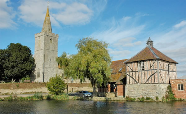
The building had been standing idle for many years and was in need of considerable repair. The owners (now our landlords) started the process of conversion to a working office building in 2002, initially spending much time working with the planning authorities to ensure the most appropriate and sensitive conversion. The reconstruction process was extensive, including replacement and repair of structural timberwork, whilst retaining as much of the original as possible, where it was sound.
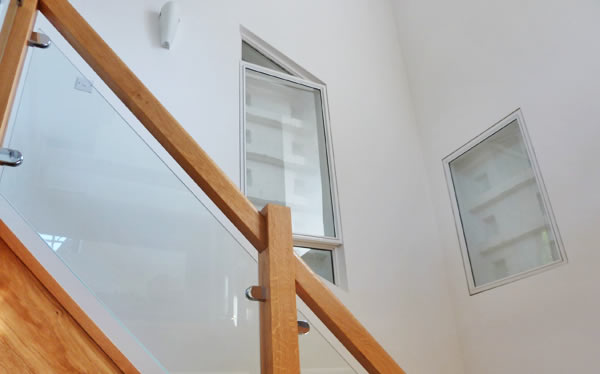
Particular consideration was given to preserving the features of historic interest. For example, although for practical purposes, the internal walls have been largely clad in studwork and skimmed plasterboard, the roosts in the brickwork have been featured in a number of locations around the internal walls with ‘display windows.’ These show off the underlying structure of the building, adding considerable character and interest to the building and helping to retain its historic charm.
During the process of conversion into useful working office space, the owners incorporated a conventional electrical installation that provides lighting and points for electric heating in a number of locations.
The KNX Plan
We decided to do the KNX conversion in three phases. Phase one would involve automated control of our lighting, and this has now been achieved. We also want to save on energy bills. The electric heating is costly to run and I feel that it will be possible to achieve significant cost savings through correct control and scheduling of the heating system’s operation. This will be undertaken in phase two of the KNX conversion. We also want to be able to monitor energy usage – in phase three – with a view to assessing and managing costs.
Phase One – Lighting
All of the building’s light switches were located together adjacent to the main door into the space. The downstairs lighting was all operated from a four-way switchplate which had fortunately been wired with the lighting ring supply fed to the switchplate and switch loops for each circuit taken from there to the appropriate light fittings.
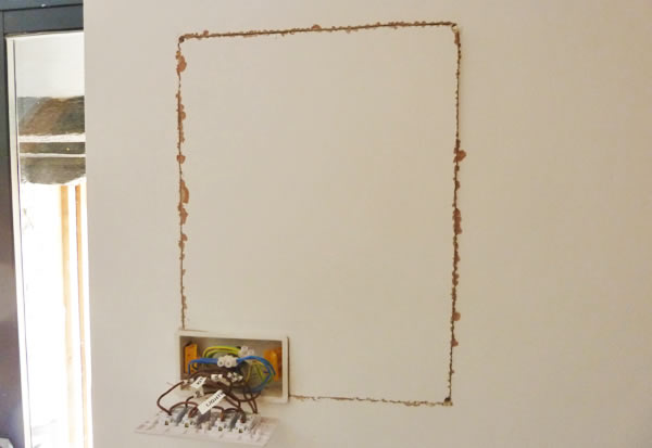
The basic lighting control using KNX has been the easiest to implement from a practical viewpoint since the conventional installation was ideally configured to be converted. The fact that the internal walls were clad in studwork meant that we could thread the cables through the void behind, which was relatively easy to do.
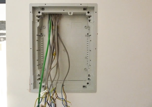
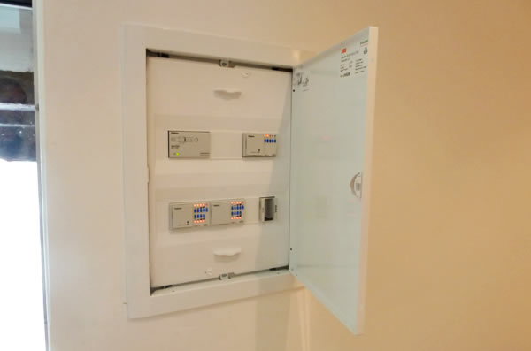
We even found that what we thought was a single group of downlights in the office area was actually wired as two separate groups connected to the same switch. This made it a straightforward conversion from conventional to KNX actuators. In principle, each of the four switches could be replaced by a KNX actuator channel, which meant that the four-way switchplate could be replaced by a flush-mounted DIN-rail enclosure for the KNX actuators and the KNX power supply. The mains supply for that power supply was taken from the lighting ring.
The low power consumption of the KNX supply – in this case, less than 10W – posed a marginal additional load in that ring circuit, that would not impinge on circuit ratings. It was decided to fit dimmer actuators for each of the three halogen downlight circuits and another for a wall light on the stairs. There is a bulkhead light outside of the front door, and it was decided that this did not need to be dimmed, so a switched-only circuit was chosen.
Dimmer modules optimised to handle the difficulties of operating with LED lighting were selected on the basis that it is fully intended over the next weeks to replace all of the halogen GU10 lamps with LED replacement lamps. The expectation is a reduction in power consumption of those circuits to less than 20% of the existing consumption.
Similarly, when we came to consider the upstairs office area lighting, which is fluorescent strip lighting, switched control was the way to go. With regard to the upstairs lighting, the wiring was such that two-way switching had originally been installed at the top and bottom of the stairs. The KNX implementation of this was to route a switch loop behind the studwork across from the four-channel switching actuator module at the new panel location.
We also routed a KNX cable across from the new panel location to the switchplate position at the bottom of the stairs. Our ultimate objective was to replace that switchplate with a KNX pushbutton sensor plate from which we would be able to control all of the lighting.
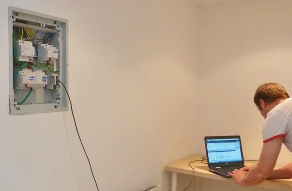
So, having made these changes, for now, a simple ETS programme has been implemented that allows the operation of each lighting circuit from the pushbuttons of the KNX sensor plate.
Next Steps
Now that we have the lighting phase of the installation installed, the next step is to add the heating control actuators and contrive a method of making the KNX connection to a much less accessible location, although hopes remain high that it will be possible to thread a cable around behind the studwork in a similar way.
Read how we got on in Part 2 of this three-part series.
Ben Lewis is Principal of KNX Consultants, a specialist in KNX control and automation offering training, mentoring, design and project work on behalf of corporate, professional and private clients. KNX Consultants is also a member of KNX UK Association.
You are welcome to comment on this article. See below.