 By Héctor Colado, Amaisys Training.
The Problem
In an automated facility, it is very common to have wall switches with an integrated status-LED for every button. The status-LED is often used to show the current status of an associated light channel, or, more commonly, to show the inverted status of the light channel, in order to be able to find the wall switch when the light is turned off.
Most wall switches set the status-LED automatically when the button is pressed, but what if more than one wall switch is being used for the same light, or the system goes through a voltage failure recovery? What we need is a reliable ‘recipe’ to ensure consistent synchronisation between the status-LED of wall switches and their associated lighting channels.
The Solution
KNX communication between devices in an installation is carried out via group addresses. In order to establish the communication between different devices, a group address should be created. To do this, link a group object of the same type from each device (from the sensor and from the actuator) to the group address.
For a specific group object, actuators can listen to several group addresses. Sensors however, can only send one group address per telegram – the rest of the group addresses associated to this group object remain as listening addresses.
Based on this principle, I will prepare a sample installation with a power supply, a three-channel switching actuator and two simple wall-switches with status-LED.
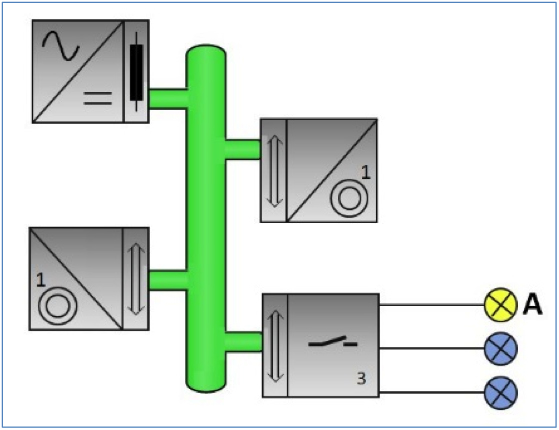
The goal is to control channel A of the switching actuator from both wall switches and show the rights steps to synchronise consistently both status-LEDs in all scenarios.
So, we will need to create group addresses for the following set of operations:
• On/Off of the switching actuator channel A (Group Address: 0/0/1 – ON/OFF LIGHT-A).
This group address is requested by the pushbutton of each wall switch to turn on/turn off the associated light.
• Status switching of the switching actuator channel A (Group Address: 0/0/2 – STATUS LIGHT-A).
This group address indicates the current status of the light. After a change, it provides the required information to synchronise the status-LED of the wall switches.
This can be achieved by performing the following steps:
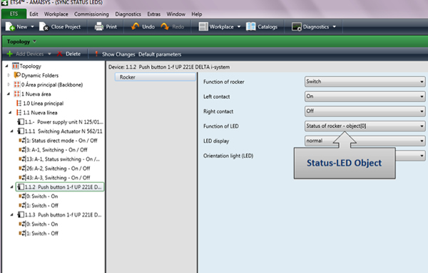
1) Configure the parameters of both wall switches to send “on/off” values and eventually, the associated object for the status-LED.
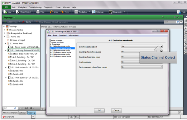
2) Configure the parameters of the switching actuator to send the switch status of the channel on change.
After that, a new group object, ‘Status switching’ will be available for the actuator.
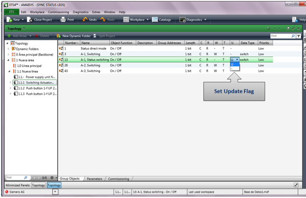
3) Confirm that the Update Flag for the ‘Status switching’ group object of the actuator is activated.
4) Link the group object ‘Switching’ from the sensors and the group object ‘Switching’ of the actuator to the ‘ON/OFF LIGHT-A’ group address.
5) Link the group object ‘Switching’ from sensors and the group object ‘Status Switching’ of the actuator into the ‘STATUS LIGHT-A’ group address.
6) Confirm that the ‘Sending’ flag for the group object of the sensors is enabled only for the ‘ON/OFF LIGHT-A’ group address.
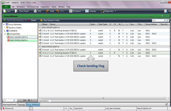
The programming above will result in the following behaviour:
A) When the button of one of the wall switches is pressed, this device will send a value of 1 to the group address (0/0/1). The switching actuator channel-A will receive the command and will turn on the light.
B) After the light is turned on, the controller will change the current switching status of the channel and then it will send a telegram (0/0/2) to the bus with the current value of the light. This value will be listened to by both wall switches, refreshing the status-LED with the new value received.
On voltage failure recovery, if the actuator was set so that the lights would return to the same status as before the failure, the actuator will send the update telegram to the bus and the mechanism will work as in (B) above.
Conclusion
The example above shows the importance of correctly configuring group addresses as sending and listening telegrams. Indeed it is essential to identify all of the possible scenarios in a facility in order to ensure the correct programming of the integrated devices. Also, the reaction of sensors to voltage failure should always be analysed separately.
Lastly, it should be noted that the new System B devices (Mask version $07B0 and $17B0) incorporate a Read on Init Flag. If this flag is set, the device will independently read the value of its sending group address at initialisation. This new functionality simplifies the required programming after a voltage failure recovery.
Additionally, when using the Update flag, bear in mind that such a flag was only introduced from KNX Devices with BCU2. Therefore, if you are using a KNX Device with BCU1, you will not find it. The solution outlined above however, is valid for all devices, including new System B devices.
Héctor Colado is a Computer Engineer and KNX++ Tutor for Amaisys Technologies (a Nechi Group Company). Amaisys provides engineering, training, consultancy and software development for smart cities and industry automation.
www.nechigroup.com
www.amaisys-training.com
If you have any comments about this, please use the ‘Leave a reply’ option below this article, and if you have a solution to a technical issue, or if you have an issue that needs to be solved send the Editor an email at info@knxtoday.com


