 By Julio Díaz, Sapienx Automation.
The Problem
A common task for many integrators is programming the KNX devices in a project with multiple lines connected via KNX TP couplers.
Sometimes we do not adequately understand the importance of a correct configuration of the KNX USB interface (local) address. When this happens, the integrator will be unable to communicate with the device to be configured. As a consequence, the installer will get the following error message:
![]()
Obviously, such messages cause frustration and lost time when downloading or unloading devices, or when carrying out other test operations.
The Solution
First of all, I must clarify that, in a KNX installation with multiple KNX TP lines, it is possible to connect the ETS, via the KNX USB interface, in any of the lines for downloading the whole installation. In order to be successful, you need to configure correctly, and in the right order, the local interface and the TP couplers.
So, while it is not obligatory to set the local interface in the main or backbone line of the system, main lines such as 1.0 or 0.0 are the logical points to do so, because we use ETS not only for downloading devices but also for testing, telegram monitoring, etc. Main lines are also typical for local interfaces because they are also used as a common point for linking the installation with others, such as visualisation systems, IP interfaces, gateways to other technologies, etc.
When we first use a local interface such as a USB interface, the physical address of this device has the default address 15.15.255. The following image, shows how to check the address of any local interface in ETS4. In the dashboard we have to select Settings –> Communication.
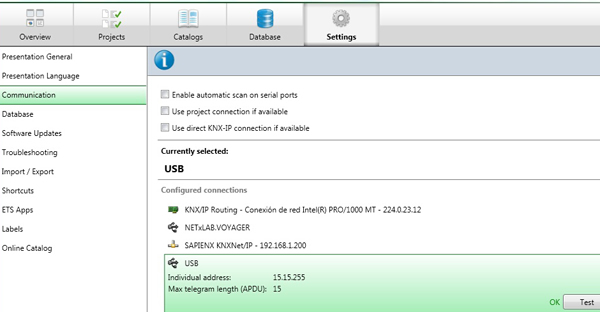
If we are programming locally some devices from one specific line, such as in iine 1.1, this default configuration of the USB interface will not cause any problems, and we can completely download all of the devices of the line without any issues.
However, as we can see in the next image, when trying to download any physical address of a device that does not belong to the line 1.1, the line coupler of this line will block this programming telegram because it filters all programming (unicast) telegrams. This is because line coupler 1.1.0 cannot admit telegrams coming from its own line with source address different from 1.1.X.
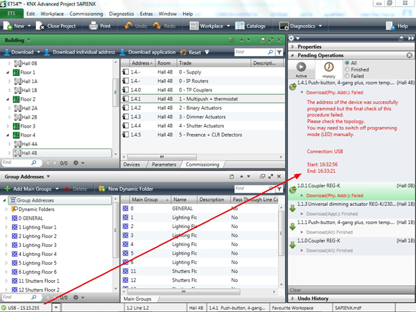
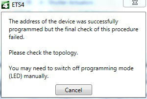
The solution is to configure the local address of the interface with the same address of the line, in this case: 1.1.X, where X = any value from 1 to 255 (we tend to use 255 as it is the common value for the local interface address).
The following image shows how to do this in the configuration of ETS4.
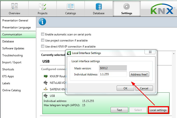
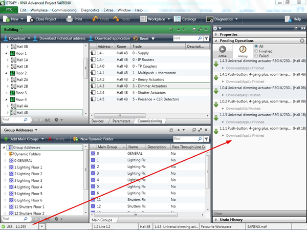
Once we have correctly configured the local address of the USB, we will be able to program devices in lines 1.1 and beyond. The following image shows several devices successfully programmed in lines 1.1; 1.0 and 1.4, where the local interface is located in Line 1.1.
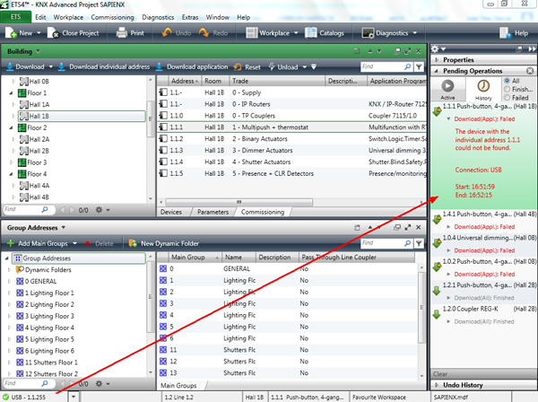
Finally, other typical mistakes when programming KNX TP installations with several lines is to change the USB interface location without adapting its local address to the new situation, For example, in this case we have moved the local USB interface to line 1.2. As the following image shows, we have been able to download local devices, but the 1.2.0 coupler rejects to program devices in lines 1.0; 1.4 and even in line 1.1.
Summary
In principle, we can program correctly any device from anywhere in the installation, when the address of the local interface and the addresses of the line couplers are properly configured.
In principle, any default physical address of the local interface does not matter when programing devices within the line where the interface is located. However, in installations with multiple KNX TP lines, i.e. installations where KNX TP line couplers come into play, the address of the local interface must always correspond to the range in which it is connected.
The KNX USB device, or local interface, can use any physical address which is not used by another device in the line (typically the local interface is set to the value X.X.100 or X.X.255, as shown in the example above).
However, if we fail to use the correct local configuration, we might experience error messages from the ETS when loading/unloading devices or when doing diagnoses.
Julio Díaz is an Electrical Engineer at Sapienx Automation, a KNX++ tutor and winner of the KNX International Award. Sapienx Automation provides engineering, training and consultancy for smart buidings, smart metering and smart cities.


